Outdoor light poles stand above people, vehicles, and nearby buildings. Their height can make them attractive paths for lightning current. Learning how to ground outdoor light poles against lightning strikes requires more than driving one rod into the soil.
Lightning researcher Martin A. Uman described lightning as “a gigantic spark that can heat the air around it to temperatures five times hotter than the surface of the sun.” That extreme energy explains why casual grounding methods can fail. A dependable design connects the pole, grounding electrode, bonding conductors, and electrical equipment into one low-impedance path. It also considers soil resistivity, conductor length, sharp bends, corrosion, and underground utilities.
This guide follows practical principles used by qualified electrical professionals. It references established approaches from standards such as NFPA 780 and IEC 62305, while recognizing that local requirements may differ. The grounding electrode should be installed where it remains stable and accessible for inspection. Connections must be mechanically secure and protected from moisture damage. Surge protective devices may also help protect LED drivers and control equipment, but they cannot replace proper bonding.
The ground may look harmless.
It is not always predictable.
A common mistake is assuming that a low resistance reading guarantees complete lightning protection. That assumption deserves reconsideration. Lightning behaves as a high-frequency impulse, so conductor routing and inductance matter greatly. Before installation, a licensed professional should evaluate the pole foundation, feeder design, bonding points, and local inspection rules. The goal is not simply to “ground the pole,” but to create a coordinated protection system that safely manages dangerous transient energy.
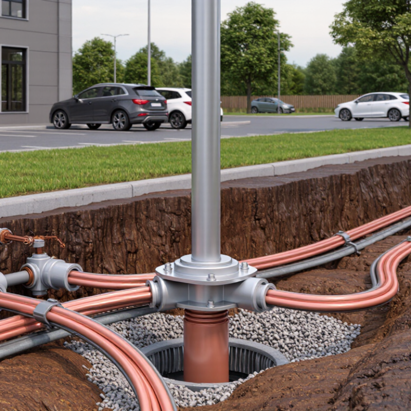
A safe light-pole installation begins with a site-specific lightning risk assessment. Review local lightning frequency, pole height, nearby trees, buildings, overhead lines, and public exposure. A pole on an open sports field faces a different hazard than one beside a tall building. Soil resistivity also matters. Dry, rocky ground may create higher grounding resistance than moist soil.
Inspect the pole’s material, foundation, wiring route, and existing grounding network. Confirm that metallic parts are bonded correctly, not merely connected by a loose or corroded clamp. A qualified electrical professional should test continuity and grounding resistance with suitable instruments. Local electrical codes and lightning protection requirements must guide the design. Surge protective devices may also reduce damage to LED drivers and control equipment.
Grounding does not make a pole immune to lightning. It provides a controlled path for fault and surge energy. The path still needs short, direct conductors and protected connections. Field conditions often differ from drawings. That is where mistakes happen. An old site plan may omit buried utilities or a damaged grounding electrode. Recheck the installation after excavation, seasonal soil changes, major storms, and equipment upgrades. Keep dated test records, photographs, and corrective actions. Small gaps deserve attention.
Grounding System Components and Their Roles
An outdoor light pole needs more than a rod driven into soil. Lightning grounding creates a controlled path for dangerous current, but it cannot prevent a strike. NOAA reports approximately 25 million lightning flashes occur annually across the United States. That exposure makes component coordination essential.
The grounding electrode transfers current into the earth. It may include a ground rod, ring electrode, or concrete-encased electrode, depending on soil and local requirements. The grounding conductor connects the pole, electrode, and service equipment. Keep it short, straight, and protected from sharp bends. A bonding jumper equalizes metal parts, reducing dangerous voltage differences around the pole base. The surge protective device protects wiring and LED drivers from remaining transient energy. It belongs at the service equipment and, where needed, near sensitive fixtures. NFPA 780 and IEC 62305 emphasize intentional bonding, suitable conductors, and verified installation practices.
A low resistance reading alone can mislead. Soil moisture changes it. Connections can loosen beneath a sealed base. IEEE guidance also stresses touch and step voltage, not only electrode resistance. Inspect clamps, corrosion, buried connections, and continuity after construction. One overlooked bond may leave a metal handhole energized. The design may look complete on paper. Field conditions still deserve skepticism. Use qualified electrical professionals and follow the locally adopted code.
Before digging, isolate the lighting circuit and confirm the pole’s metal body is electrically continuous. Follow local electrical codes and use a qualified electrician for the installation. NOAA’s National Weather Service reports about 20 lightning deaths in the United States each year. A pole can become a dangerous current path within seconds.
Choose a grounding electrode based on soil conditions and local requirements. Drive the electrode vertically where possible, leaving the connection accessible for inspection. Run a suitably sized grounding conductor from the pole’s grounding point to the electrode. Keep the route short, direct, and free from tight bends. Bond the pole, handhole hardware, and other exposed conductive parts together. Use listed connectors designed for outdoor corrosion and lightning exposure. NFPA 780, 2023 edition, emphasizes continuous bonding and properly installed grounding electrode systems.
Test the completed system with calibrated equipment, then record the reading, weather, soil condition, and connection points. A low resistance reading alone does not prove effective lightning protection. This is where rushed work often fails. I have seen clean-looking installations with loose clamps hidden below grade. Inspect those connections again after severe storms and during scheduled maintenance. IEEE guidance also stresses equipotential bonding, so nearby metallic fences, cabinets, and service grounding should not remain electrically isolated. Never treat a grounding rod as a complete protection system. Review the design when soil, pole height, wiring, or site conditions change.
How to Ground Outdoor Light Poles Against Lightning Strikes
A grounded light pole needs more than a rod driven into soil. The pole, grounding electrode, equipment grounding conductor, and service enclosure should share a low-impedance path. Bonding is different. Bonding connects metal parts so lightning energy does not jump across loose hardware or painted joints. A recurring field finding is a ground wire attached to the pole, but not bonded to the access door or nearby metal conduit. That gap can create dangerous side flashes.
Keep it short. Use a continuous copper grounding conductor where local electrical rules permit it. Protect the conductor from physical damage, and clean contact surfaces before tightening listed connectors. The National Weather Service reports about 20 lightning fatalities and hundreds of injuries annually in the United States. That makes connection quality more than a maintenance detail. It is a life-safety concern. However, grounding alone cannot stop induced surges. Install a suitable surge protective device at the lighting circuit panel, and consider additional protection near sensitive LED drivers. The International Electrotechnical Commission’s lightning protection guidance emphasizes coordinated bonding, earthing, and surge protection rather than one isolated component.
NFPA fire-loss research has linked lightning to thousands of structure and outdoor fires over reported periods, with substantial property damage. Inspectors should check corrosion, soil movement, loose lugs, and damaged insulation after severe storms. Details matter. A common weakness is assuming a larger electrode automatically improves protection. Soil conditions, conductor routing, impedance, and bonding continuity may matter more. Have a qualified electrician verify the design against current local requirements and test continuity before energizing the pole.
Lightning current crest values span a wide range. A properly grounded outdoor light pole should have a continuous grounding path, bonded metal parts, short and straight electrical connections, and coordinated surge protective devices. These statistical values are for context only and do not replace local electrical codes or engineering calculations.
Reference: Statistical lightning-current distribution described in IEC 62305-1. Values represent approximate lightning-current crest levels by probability.
A grounding system for an outdoor light pole needs regular testing, not just installation. Inspect the grounding conductor for cuts, loose lugs, corrosion, and physical damage. Check every bonding point between the pole, equipment cabinet, and grounding electrode. A missing washer or painted connection can interrupt the path during a lightning event.
Use a calibrated ground resistance tester according to the manufacturer’s method and local electrical requirements. Do not rely on one universal resistance value. Soil moisture, electrode depth, and system design affect the result. Test during dry conditions when practical, then record the weather, instrument, test method, and reading. A single good reading can mislead. Compare new results with earlier records instead.
Inspect the system at least annually and after a nearby lightning strike, excavation, pole replacement, or major soil disturbance. Look for melted insulation, scorch marks, cracked concrete, and displaced conductors. Tighten connections only after confirming the circuit is safely isolated. A qualified electrical professional should investigate unstable readings or damaged components. Some maintenance work is easy to underestimate. A rushed inspection may miss corrosion hidden beneath a clamp. Keep dated photographs and test reports, so future technicians can identify gradual changes and question unusual results before they become failures.
Each site has different risks. An open sports field, nearby trees, buildings, and overhead lines change lightning exposure. Soil conditions matter too.
Check lightning frequency, pole height, nearby structures, public access, wiring routes, and soil resistivity. Dry, rocky ground may increase grounding resistance.
No. A rod is only one component. The pole, grounding conductor, electrode, service enclosure, and exposed metal parts need a coordinated path.
Bond the pole, access door, handhole hardware, conduit, and nearby cabinets. Use approved outdoor connectors. Painted joints and loose clamps can interrupt continuity.
Keep it short, direct, and protected. Avoid tight bends. Clean contact surfaces before tightening connections. Hidden corrosion can defeat good-looking work.
Yes, where suitable and required. Install protection at the lighting panel, with additional protection near sensitive control equipment when needed.
A qualified electrical professional should test continuity and grounding resistance using calibrated equipment. Record readings, weather, soil conditions, and connection points.
Recheck it after severe storms, excavation, seasonal soil changes, and equipment upgrades. Inspect loose lugs, damaged insulation, corrosion, and soil movement.
No. It does not confirm bonding quality or surge control. I once trusted a clean reading too quickly. That judgment deserves reconsideration.
A ground wire may connect to the pole but not the access door or metal conduit. That gap can force surge energy across hardware.
This guide explains how to ground outdoor light poles against lightning strikes by combining careful risk assessment, properly selected grounding components, and reliable installation practices. It begins with evaluating the site, pole height, soil conditions, exposure, and nearby structures to determine the level of lightning protection required. Key components may include grounding electrodes, conductors, bonding connections, and inspection points, each serving to provide a low-resistance path for electrical energy to dissipate safely into the earth.
The installation process covers placing grounding electrodes, connecting them securely to the pole, and ensuring that all metallic parts are bonded together. It also highlights the importance of surge protection devices and correctly rated electrical connections to help reduce damage to lighting equipment. Finally, the guide emphasizes testing grounding resistance, inspecting connections for corrosion or looseness, and maintaining the system regularly. Consistent inspections and timely repairs help preserve protection and improve the long-term safety and reliability of outdoor light pole installations.

Lukas Lighting